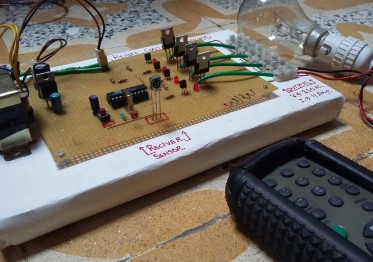
Project Information
The circuit of the IR Remote Controller Fan Regulator using AT89C2051 is very simple and straightforward, thus there are no difficulties to understand for one who is familiar with the microcontroller. For more simplicity, we had divided the entire circuit into three main sections.
- Power Supply
- IR Sensor
- Control Unit
Power Supply | IR Remote Controller Fan Regulator using AT89C2051
The circuit of the power supply unit for the IR Remote Controller Fan Regulator using AT89C2051 is designed around a center-tapped transformer, rectifier diode, series voltage regulator (7805), and capacitor. Basically, the power supply circuit is designed using a full-wave rectifier.
The AC mains input (230V) is connected to the primary winding of X1. The main function of the transformer is to lower the voltage to the desired level (12V-0-12V). The secondary terminal (output) of the transformer is connected to the diode for rectification. The pulsating DC is further filtered by capacitor C1 before being given to the relay. This filtered output is further changed to +5V using a series voltage regulator (7805) for the microcontroller and other circuit components, as shown in circuit diagram figure 1. LED1 is used to indicate the power supply.
IR Sensor | IR Remote Controller Fan Regulator using AT89C2051
Here we have used TSOP1738 to detect IR signals transmitted from the remote. For simplicity of the circuit, we had used an IR remote available in the market rather than a transmitter circuit. The IR signal generated by the IR remote is detected by the IR receiver (TSOP 1738) and sends the output pulse to the receiver pin (pin 2) P3.0 of the MCU (AT89C2051).
Control Unit | IR Remote Controller Fan Regulator using AT89C2051
The heart or main part of the project IR Remote Controller Fan Regulator using AT89C2051 is the MCU (AT89C2051). Here in this project, the MCU recognizes the signal from the IR receiver and further controls the output. AT89C2051 is a 20-pin DIP MCS-51 family chip having 2Kb and 128 bytes of memory for flash ROM and RAM, respectively. Transistors T1, T2, and T3 connected to the output pin of the MCU, as shown in figure 1, are used to drive relay RL1, RL2, and RL3, respectively. These relays are used to control the speed of the fan using resistors R6 through R9.


Reviews
There are no reviews yet.